<< Solar Bubble Build Home
Tourniquet Skin Fastening
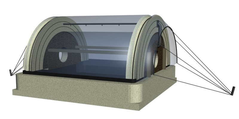
Simple rope tourniquets hold the skins in position creating a airtight seal around the radius of the end walls and cavity spaces. This tourniquet also produces tension along the axis on the tunnel skins.
Liquid Seals
The loose bottom skin edges are held by lacing beneath the solution level in the tank producing a liquid seal.
Soap Tank / Thermal Mass
The thermal mass in this test cell is the shallow base tank containing soap solution. Having had many problems and efficiency losses transferring heat from soap tank to a separate thermal mass in my current project, i feel the extra expense of soap concentrate in these small cells is worth it.
Even Stored Heat Energy Release
Being as the entire floor area of the cell is the thermal mass any heat energy that is stored or added to the system can be very evenly distributed to the interior space. There are no hot spots in the system making monitoring and calculating heat loss more accurate.
Slow Continuous Bubble Generation
Bubble regeneration cycles which uses air blower bubble generation causes large temperature fluctuations within the cavity space causes very variable thermal dynamics within the bubble insulation as a whole. I suggest we use instead a slow continuous bubble generation from compressed air. Air is released along the length of the bottom of one side of the cavity space from a perforated tube. Air is supplier from the another perforated tube on the adjacent bottom side, above water level, via a compressor. Bubbles slowly build from the air outlet side and travel over the tunnel in a continuous moving blanket. The speed of this blanket can be regulated by the rate of bubble destruction on one side and generation on the other. Controlled destruction could be achieved be a simple slow moving revolving shaft with paddles attached to its length. It may be the case that this will not be necessary as the bubbles will have drained down fully by the time they reach the other side and will be very fragile. The pressure created from entering new bubbles might be sufficient to collapse bubbles at the bottom on the destruction side.
Simple Skin Pattern
Both inner and outer skins are simple rectangles keeping wastage to a minimum and surface area calculations, needed for heat loss measurement, simple.
Fibre Glass Tank
I learned from my current project that soft bodied gutters and bladders can cause major problems, usually at the worse possible moments. Twice I’ve dropped my screw driver into the bottom poly return gutter in my project causing punctures. I’m confident hard walled liquid containment is the only way to ensure a reliable system.
Soft + Rigid Laminations
Like with artists foam board the combination of thin, flexible but non-compressible sheets and layers and soft, flexible foam can be laminated together to make stable composite members. 6mm ply would do fine for this although I’m not sure were to source flexible insulation foam, although I’m sure something suitable must exist.
Test Rig
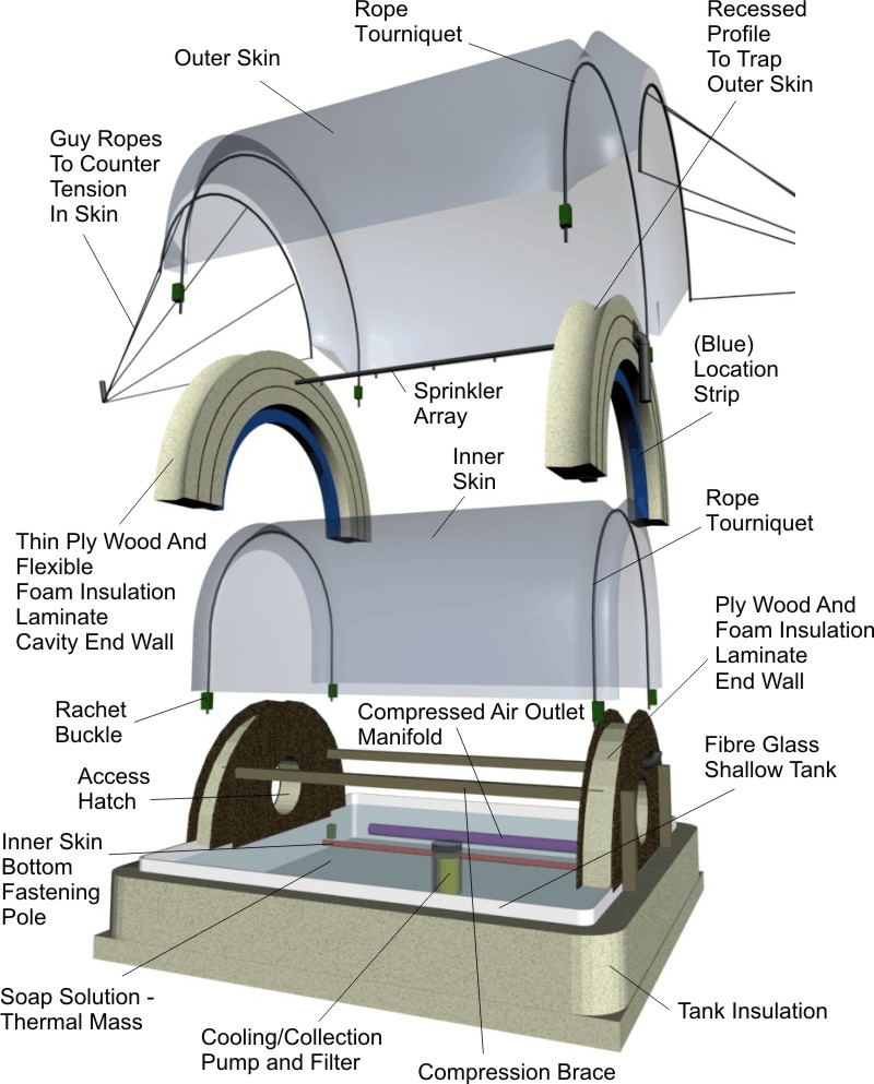
Diagram Amendment Notes
*(Not shown in the diagram below) The end walls could extend a short way down beneath the water level and thus the entire cavity space would be entirely air tight, if not at lease draught tight.
*A skirt around the base of the outer skin would be required to complete the weather proofing of the base tank. This skirt would pass from the outer skin to the outside of the tank insulation where it could be fastened using lacing to provide further tension in the skin.